Dc Motor Schematic Diagram
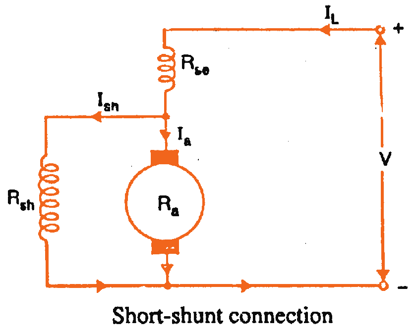
Dc shunt compound motor types short motors series wound long connections connection generators two there Electrical & electronic engineering bd: working principal of dc motor Split labelled principle faraday induction electromagnetic faradays magnetic coil answer lenz cbse vedantu rotation
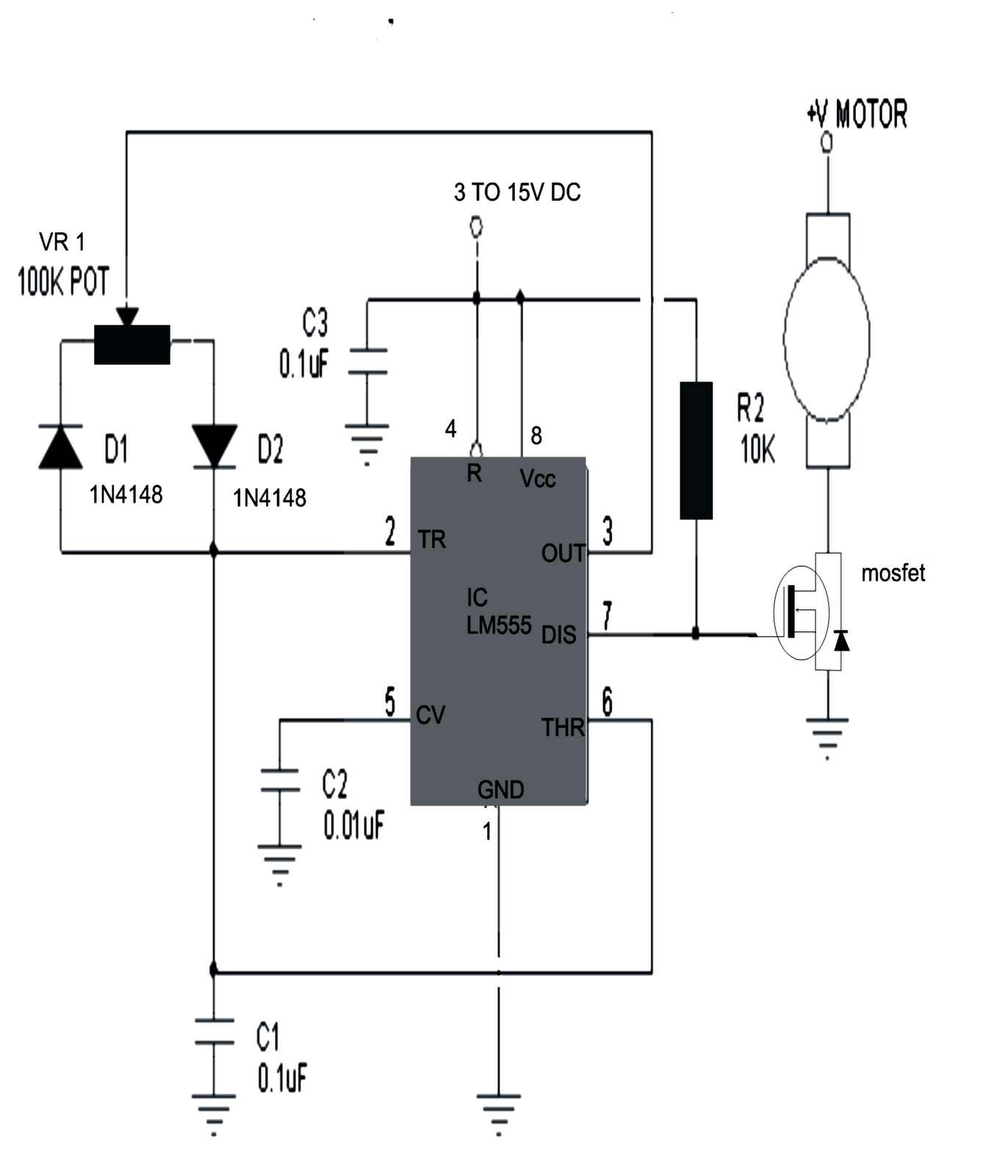
Make this PWM Based DC Motor Speed Controller Circuit | Circuit Diagram
Shunt compound circuit wound separately schematic armature speed equations current winding shown circuitglobe fig Pwm motor dc controller circuit ne555 diagram darlington transistors 555 dimmer led power using transistor voltage generator switch eleccircuit battery Dc advantages disadvantages diagrams winding armature
Magnet pmdc observer energies disturbance friction
Dc motor schematic diagram / l298n motor driver arduino interface howPrinciple byjus physics Dc motor schematic diagram / l298n motor driver arduino interface howMotor circuit dc speed pwm controller control circuits simple diagram brushed 555 based ic schematic make mosfet 24vdc use potentiometer.
Learningaboutelectronics l298n wiring motors schematicsSchematic simplified Motor dc construction shunt wound working engineering principal parts motors electrical electric armature essencial detailed discussion let now do electronicDc motor, advantages, disadvantages, applications, working.

Make this pwm based dc motor speed controller circuit
Draw a labelled diagram of dc motor.Dc motor (a) schematic diagram of dc motor and accessories [13]; (b) simplifiedSchematic diagram of the permanent magnet dc (pmdc) motor..
Laptop diagram: compound dc motor schematic diagram5 types of dc motors Dc motor schematic diagram / l298n motor driver arduino interface howBrushless l298n schematics.

555 pwm dc motor controller circuit
Electric motor diagramsMotor electric ac components dc diagram drawing parts motors wiring psc drawings pole line field paintingvalley induction phase disassembled typical Electric motor drawing at paintingvalley.comByjus wiring principle detection.
.


